Application of ozone generator in drinking water treatment and disinfection
Ozone generator is a device that uses ozone (O3) for water treatment, which can effectively improve water quality standards. Ozone is a strong oxidant with the ability to efficiently kill, disinfect, decolorize, deodorize, and decompose organic pollutants. It is widely used in the field of drinking water treatment.

Overview of Ozone System Design
The 12k/h oxygen source ozone system of Sankang Company mainly includes an ozone generator, a front ozone dosing system, a rear ozone dosing system, a tail gas ozone depletion system, a detection and PLC monitoring system, instrument air and liquid oxygen replenishment air system
Provide an oxygen rich gas source with an oxygen concentration of over 90% on site, with a pure oxygen gas source as a backup. When in use, add about 5% compressed air as nitrogen supplement to make the oxygen concentration around 95%. The gas source is filtered through dust removal to remove dust larger than 0.0l um. The inlet pipeline is equipped with shut-off valves, safety valves, dew point detection, pressure sensors, pressure gauges, etc. Oxygen is converted into ozone through an ozone discharge chamber, and then transported to the ozone transmission pipeline through ozone concentration detection, flow detection, and regulation. The outlet pipeline is also equipped with temperature sensors and pressure gauges.
The ozone power supply device outputs a power supply with a voltage of about 4kV and a frequency of about 800Hz to the ozone discharge chamber, forming a medium frequency high voltage electric field in the discharge unit to convert O2 into O3. The ozone power supply device comes with a PLC control system, which can achieve local automatic control of the well and communicate with the main control PLC
Ozone workshop is equipped with ozone leakage alarm and oxygen leakage alarm. If the ozone or oxygen leakage in the workshop exceeds the standard, the alarm will detect and send out a signal alarm. The well can also start the workshop exhaust system at the same time
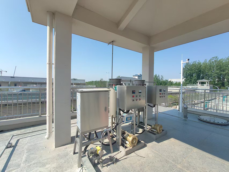
The design of the front ozone contact tank is divided into two parallel dosing lines, each line is equipped with a set of ozone dosing units, using jet dosing, consisting of a booster pump, jet injector, flow meter, electric control valve, pneumatic cut-off valve, pressure sensor, pressure gauge, etc. Two sets of ozone dosing units are uniformly controlled by the PLC of the front dosing control cabinet, and are controlled by the front dosing control cabinet according to the set water supply flow rate and dosing ratio Automatically adjust the dosage of ozone. The booster pump is designed for dual use and one backup, with two feeding lines simultaneously feeding ozone into the front ozone contact tank. The pneumatic cut-off valve of the ozone feeding unit automatically shuts off according to pressure, effectively preventing water from flowing back into the ozone delivery pipeline
The design of the post ozone contact tank is divided into two sections for operation, with one ozone dosing line designed for each section. Each line is equipped with three dosing points, and the dosing ratio of ozone at the three points is 60% (with a regulating range of 40-80%), 20% (with a regulating range of 10-30%), and 20% (with a regulating range of 10-30%) of the dosing amount in the direction of water flow. Micro porous aeration discs are used for ozone dosing. Each ozone dosing line is designed with a set of ozone dosing control units, consisting of flow meters, electric regulating valves, pressure gauges, etc. The two sets of ozone dosing units are uniformly controlled by the PLC of the post dosing control cabinet, and the amount of ozone dosing is automatically adjusted by the post dosing control cabinet according to the set water supply flow rate and dosing ratio. The ozone dosing control scraper is uniformly set in the main control PLC cabinet, and the main control PLC sends control instructions to the rear dosing control scraper cabinet. The micro porous aeration plate is evenly distributed inside the rear ozone contact tank, and ozone gas is uniformly injected into the water through the hungry hole aeration plate
The post ozone contact tank is also equipped with multiple sampling ports, which can be used to detect the remaining ozone concentration in the water. The control scraping system can also automatically adjust the amount of ozone added by detecting the ozone concentration in the water.
To ensure pressure balance inside and outside the front and rear ozone contact tanks, bidirectional safety valves are installed at the top.
Two tail gas ozone disruptors are designed for the front and rear ozone pre dosing systems, one in use and one as backup, to ensure that the concentration of ozone discharged into the ambient atmosphere is below 0.1ppm. The exhaust ozone disruptor has an exhaust ozone concentration monitor at the outlet and a sampling port at the inlet. The exhaust concentration is monitored by a portable ozone concentration monitor. When the exhaust concentration is high, the ozone dosage can be reduced by adjusting the system settings

Oxygen source 12kg/h Ozone generator
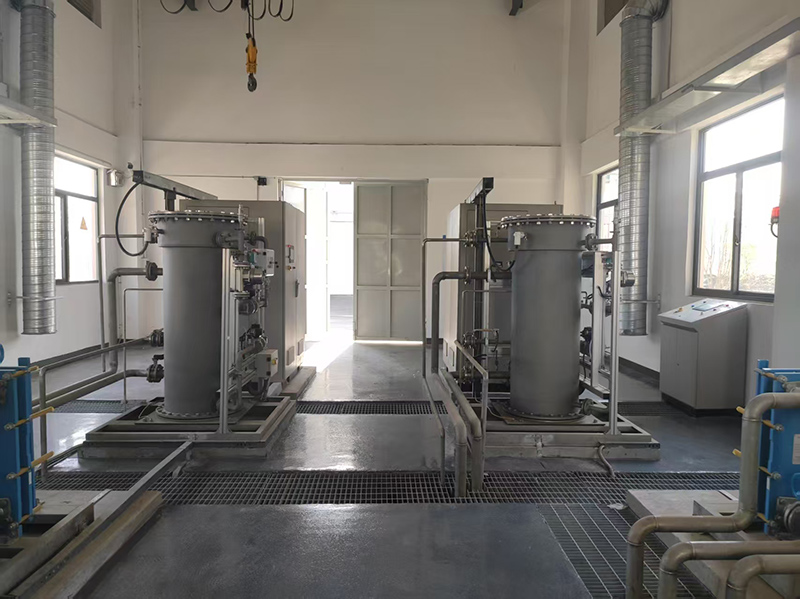
The ozone generator adopts the 12kg/h large medium frequency ozone generator independently developed by Sankang Company, which is mainly composed of ozone discharge chamber components and ozone power supply devices.
Main technical parameters
The technical parameters for the installation of this equipment are designed according to the bidding documents: ozone production ≥ 20 kgO3/h, ozone concentration ≥ 8.0wt%; Power consumption 7.8-leOk Wh/kgO3
Sankang's current ozone technology has reached a power consumption of ≤ 10kWh/kgO3 under the condition of ozone concentration ≥ 10wt%
Ozone discharge chamber
On the basis of the conventional 12kg/h ozone generator discharge chamber structure and technology, the cooling process of the discharge chamber and the assembly process of the discharge body have been improved to enhance the cooling efficiency of the discharge chamber. The discharge body has been strictly screened, and the capacitance value of each discharge unit is close to the same, which is more conducive to the production of high concentration ozone.
Pre ozone dosing system
The front ozone dosing system is designed with 3 booster pumps (2 in use and 1 backup), 2 sets of ozone dosing control units for well connected operation, 2 tail gas ozone decomposers (1 in use and 1 backup), 2 bidirectional safety valves, and 1 dosing control cabinet. The dosing control cabinet automatically adjusts the ozone dosing amount and the working/backup status of related equipment through setting, and communicates with the main control PLC
6. Post ozone dosing system
Post ozone contact tank
The post ozone contact tank is designed to operate in two compartments, with a treatment capacity of 4167m3/h. The ozone dosing device uses alumina aeration heads, and a total of 96 aeration heads are designed based on the aeration volume and service area. The pore size of the aeration micropores is 10-15 µ m, producing microbubbles with a size of 1-2mm. Due to the design of one ozone dosing line per grid, each line is equipped with three dosing points, and the dosing ratio of ozone in each section is 60%, 20%, and 20% in the direction of water flow. The number of aeration discs used for the three dosing points is 26, 11, and 11, respectively
Each grid is designed with 1 bidirectional safety valve, for a total of 2 valves. Each ozone dosing line is designed with one set of ozone dosing control unit
Design 2 tail gas ozone decomposers for the post ozone contact system, with 1 backup and 2 defoggers.
Ozone dosing control unit
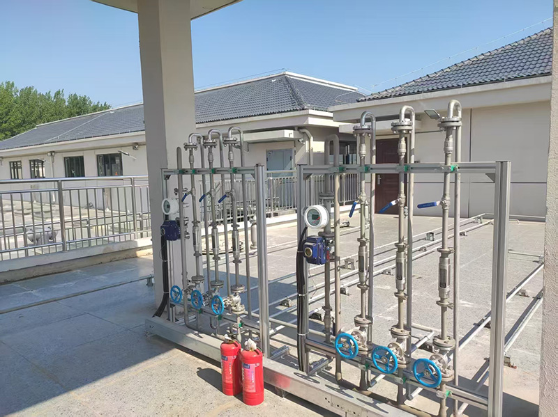
Ozone gas is passed through pipelines to the top of the ozone contact tank and divided into two paths to enter each ozone dosing line, each equipped with a set of ozone dosing units. Each set of ozone dosing unit is detected and regulated by an ozone flowmeter and an electric control valve, and then divided into three branch pipelines. After each branch pipeline flowmeter detects its own flow rate, it enters three dosing points. Each branch is equipped with a flowmeter; Equipped with manual regulating valves and pressure gauges for gas volume control and pressure detection, controlling the ozone dosage at each point.
Exhaust ozone decomposer
As ozone is a harmful gas, the undissolved ozone in the exhaust gas needs to be removed to meet the allowable ozone concentration standards in the environment. Two exhaust gas disruptors are installed in each of the front and rear ozone systems, one in use and one as backup
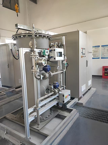
Ozone tail gas destruction adopts a heating catalytic hybrid tail gas ozone decomposition method, which mainly decomposes excess ozone in the tail gas through catalytic decomposition. It consists of catalytic reaction tank, heater, temperature controller, centrifugal fan, detector, control system and other components. In addition to manual control on site, remote automatic control can also be achieved by PLC
The exhaust gas is preheated before entering the catalytic reaction tank to prevent the formation of liquid water due to condensation during the process. The heater is controlled by a temperature controller to ensure that the system operates within the set temperature range. Ozone molecules in the catalytic reaction tank are decomposed by the catalyst, and the ozone removed exhaust gas is extracted from the catalytic bed by a centrifugal fan and discharged into the atmosphere
The tail gas ozone decomposer is controlled by on-site PLC for automatic operation, achieving on-site manual/automatic monitoring of the operation of the ozone tail gas disruptor, and communicating with the main control PLC of the ozone system to achieve remote monitoring function


